

Designing a ventilation system for a dark out tunnel ventilated rearing house can be challenging. There are many different models and designs of light traps available, each with different light restriction capacities.
Andrew Bourne, World Technical Services Specialist, Cobb-Vantress
The air flow restriction does not necessarily correspond with the light reduction factor. Some light traps with very high light reduction factors have very low air flow restriction. The amount or area of light trap needed will primarily depend on the fan capacity needed to achieve the target house velocity.
Light traps or light filters can be compared in terms of two criteria:
Resistance to airflow
Resistance to air flow is usually presented in graphical format with static pressure (in Pascals (Pa) or inches of water column (in wc)) plotted against light trap face velocity in meters per second (m/s) or feet per minute (fpm). When comparing light traps at a given face velocity, a lower static pressure will indicate a lower air flow resistance.
Resistance to light transmission
Test facilities will place high wattage lamps outside the light traps to simulate direct sunlight. Light intensity is measured at the outside and inside surfaces of the light traps. The light reduction factor is calculated by dividing the outside light intensity by the inside light intensity.
When comparing different light traps/filters, the higher the light reduction factor, the greater the resistance to light transmission. The light trap should have a light reduction factor of at least 2,000,000 to one. Ideally it should be in excess of 10,000,000 to one.
Some general light trap choices and installation tips
- Light traps are available in both a cellular and blade design.
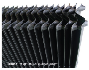 Blade or vane type light traps are suitable for fan installations. They must be installed with the vanes vertically orientated to prevent dust accumulation. Cellular types are not suitable for fan installations, but can be used in perimeter and tunnel inlets. Cellular types are more difficult to clean and disinfect.
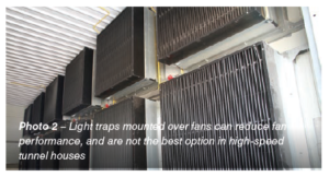
 - Light traps placed directly over fans will cause a significant drop in fan performance, thus they are not the best option in a high-speed tunnel houses.
 In a cross ventilated pullet house, a 150 cm × 150 cm or 2.25 m² (60 in x 60 in or 25 ft²) light trap can be placed directly over a standard 120 cm fan (48 in). The light trap must be mounted at least 25 cm (10 in) from the fan shutter.
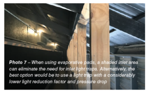
 - When installing both tunnel inlet light traps and evaporative pads in a pullet rearing house,
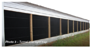 the tunnel inlet light traps can have a lower light reduction factor and lower air flow resistance than those installed at the tunnel fan end, due to the light reduction factor offered by the evaporative pads and a darkened dog house (painted black or the use of shade cloth).
 - An efficient installation option for the tunnel fan light traps,
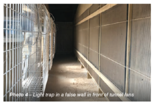 is to construct a false wall that incorporates the light traps, placed 1.5 m (5 ft) from the tunnel fan end. This allows air to pass through all light traps reducing the pressure drop when the house is not in full tunnel mode.
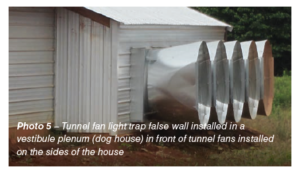
 - An alternative is to install the tunnel fans on the sides of the house, each with a plenum type room (doghouse) for the installation of the light trap false walls.
 This is by far the most efficient, since fan and light trap area requirements in high speed rearing houses usually require more light trap area than can fit into the house cross section.
 - Perimeter inlet light traps are installed in a windproof box/cover on the outside of the house.
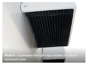 The cross sectional area of this box/cover should be at least 30% larger than the perimeter inlet itself. The light traps are similarily sized to fit into the opening of the box/cover.
Rearing house air velocity and operating pressure standards
House air velocity standards
Pullet house air velocity requirement: 2.0 to 2.5 m/s (400 to 500 fpm)
Rear, grow, lay house air velocity requirement: 2.5 m/s to 3.0 m/s (500 to 600 fpm)
Operating pressure drops standards
- The target pressure drop across the tunnel inlet light trap is 5 Pa (0.02 in wc). This will vary depending on suppliers and the required light reduction factor.
- The installation of an evaporative cooling system increases the pressure drop by 12.5 Pa (0.05 in wc).
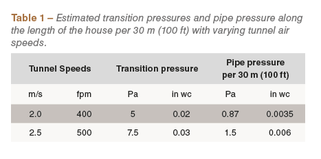
- Generally the transition pressure drop (turn pressure drop, caused by drawing incoming air through a large inlet area and squeezing it into the smaller house cross section) will contribute a combined 5.0 to 7.5 Pa (0.02 to 0.03 in wc).
- Pipe pressure produced as the air moves down the length of the house will depend on velocity– see table above for estimates per 30 m (100 ft) of house length.
- Any extra equipment or obstructions over the length of the house could also potentially increase the house pipe pressure – if possible, do not use obstructive equipment. This is particularly relevant for combined rearing and production houses. Therefore, if possible, keep nest boxes outside the house during rearing.
- The target pressure drop across the tunnel fan light trap is 20 Pa (0.08 in wc) (This will vary depending on suppliers and the required light reduction factor).
- When installing light traps, it is very important to know the pressure drop across the light trap. Use this information to ensure the correct fan capacity is installed to meet the air velocity requirements of the flock.
- The light trap supplier will supply the expected pressure drops (Pa or in wc) over a range of face velocities (m/s or fpm).
- The airspeed or face velocity of the light trap is a representation of its area relative the total tunnel fan operating capacity.
- Ideally the sum of all the pressure drops, or the total amount of work the fans need to do, should not exceed 37.5 Pa (0.15 in wc).
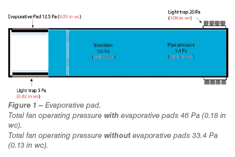
The pressure readings will increase from the front to the extraction end of the house. The pressure reading at the extraction end is an indication of the amount of work the fans must do to move the air down the length of the house. It is the sum of the following pressure drops: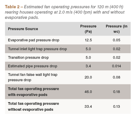
- evaporative pad pressure drop;
- tunnel inlet light trap pressure drop;
- transition or “squeeze” pressure drop;
- pipe pressure drop, (including resistance created by objects such as nest boxes and feed hoppers)
- tunnel fan light trap
A rearing house without evaporative cooling should ideally operate at about 37 Pa (0.15 in wc) in full tunnel mode. In reality this can be achieved if the house is designed for 2 m/s (400 fpm), but is very difficult to achieve if an air velocity of 2.5 m/s (500 fpm) is needed. If an evaporative cooling system is installed, and air velocity is increased to 2.5 m/s (500 fpm), the house operating pressure will be more than 50 Pa (0.25 in wc) in full tunnel ventilation.
Light trap sizing example – Rearing house without evaporative pads
Information needed from equipment suppliers includes:
- Tunnel fan capacity at pressure to ensure required air speed is achieved
- Light trap pressure and face velocity curves – this will be used to calculate light trap area requirement.
Tunnel fan capacity at pressure to ensure required air speed is achieved
Rearing house dimensions for this example: 120 m × 12 m × 2.4 m (cross section area – 29 m²)
400 ft × 40 ft × 8 ft (cross section area – 320 ft²)
Tunnel fans in this example: Cone fan 1.44 m (57 in)
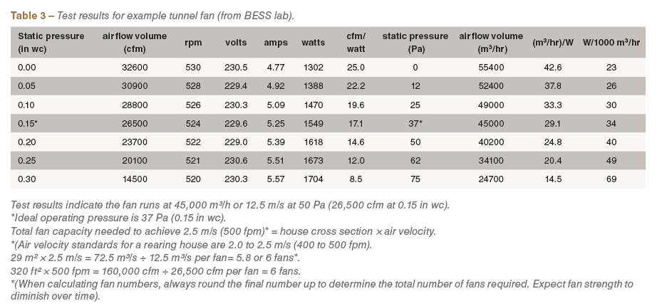
Test results indicate the fan runs at 45,000 m³/h or 12.5 m/s at 50 Pa (26,500 cfm at 0.15 in wc).
*Ideal operating pressure is 37 Pa (0.15 in wc).
Total fan capacity needed to achieve 2.5 m/s (500 fpm)* = house cross section × air velocity
*(Air velocity standards for a rearing house are 2.0 to 2.5 m/s (400 to 500 fpm).
29 m² × 2.5 m/s = 72.5 m³/s ÷ 12.5 m³/s per fan= 5.8 or 6 fans*
320 ft² × 500 fpm = 160,000 cfm ÷ 26,500 cfm per fan = 6 fans
*( When calculating fan numbers, always round the final number up to determine the total number of fans required. Expect fan strength to dimish over time.)
Light trap pressure and face velocity curves – calculating light trap area requirement
The graphic illustration below is an example of a BESS LAB test results for a vertical blade type light trap.
- The pressure drop across the light traps and light reduction factor were measured over a wide range of face velocities.
- The light trap face air velocities used for calculating the areas of light trap for both inlet and tunnel fan false wall were extrapolated from the pressure curve.
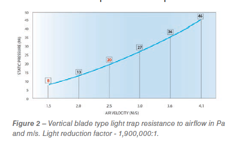
The tunnel inlet light trap was sized at 1.5 m/s (300 fpm) with a pressure drop of 8 Pa (0.03 in wc). The tunnel fan light trap was sized at 2.5 m/s (500 fpm) with a pressure drop of 20 Pa (0.08 in wc). See the values highlighted in red.1
Sizing the light traps
As a general rule both the tunnel inlet and fan false wall light traps can be sized over a range of face velocities. The tunnel inlet light traps can be sized at 1.5 to 2.5 m/s (300 to 500 fpm) and the tunnel fan false wall light traps at about 2.5 to 3.8 m/s (500 to 700 fpm). This can vary depending on suppliers and the required light reduction factor. The area of the light trap will always depend on the amount of fan capacity installed.
Sizing the tunnel inlet light trap
Based on our standard requirements in terms of maximum house pressure drop to not exceed 37 Pa (0.15 in wc), the tunnel inlet and tunnel fan light traps are sized at 1.5 m/s (300 fpm) and 2.5 m/s (500 fpm), respectively.
Tunnel fan capacity installed: 6 x 12.5 m³/s (26,500 cfm) = 75 m3/s (159,000 cfm)
Tunnel inlet light trap area needed: 75 m³/s ÷ 1.5 m/s = 50 m²
159,000 cfm ÷ 300 fpm = 530 ft²
Tunnel fan light trap area needed: 75 m³/s ÷ 2.5 m/s = 30 m²
159,000 cfm ÷ 500 fpm = 318 ft²
Potential problem
The cross section of the house used in the example is 29 m² (320 ft²). Installation of 30 m² (332 ft²) of tunnel fan light trap false wall will be impossible since the light traps need to be mounted on a concrete stem wall above the litter. This problem will be further compounded in a combined rearing and production house with slats.
Solution
An alternative is to install the tunnel fans on the sides of the house with a plenum type room (dog house) for the installation of the light trap false walls (see light trap choices and installation tips E).
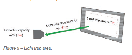 Note: when sizing a light trap to be installed across a perimeter, tunnel inlet or in the light trap wall in front of the tunnel fans, the area of trap required is a function of the air velocity required across the inlet or light trap wall. The larger the area the lower the pressure drop.
Light trap area m2 (ft2) = Tunnel fan capacity m3/s (cfm) ÷ Light trap face velocity m/s (f/m).
Conclusions
The choice and installation of light traps are very important when upgrading or in new builds. In many parts of the world where rearing and production are in the same house, the light traps need to be removed at light stimulation. Choosing a high quality modular light trap that can be easily dismantled and safely stored is critical. In the future, with increases in stocking densities and the need for higher air velocities in rearing, the choice and sizing of light traps will become important for successful management during hot weather.
1 These pressure and velocity values in the graphs are estimates of the values published by BESS LAB. The pressure and face velocities used are only close approximations – for more accurate data contact your light trap supplier.


